
|
The Miniature, Rugged Alternative to LVDTs and Linear Potentiometers
|
Order • About • Site Map |
|
|||||||||
Position Transducer Linearity (Calibration) Calculator |
|
Tip: Use the Tab key to move field to field.
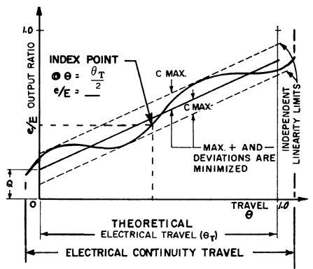
What Does The Above Calculator Tell Me?The above calculator is also known as a "10-point calibration" (technically, you are providing 11 points). It will tell you how linear your position transducer (or any other set of data) is. It requires you know the calibration range of the unit and that you provide a known reference signal (Excitation). It also requires 11 points of data per the Step columns. What is Linearity?As applied to a position transducer, linearity is a measure of the deviation from a straightline ("perfection") of the position transducer's electrical output versus its mechanical position. The VRCI-P-100A Precision Potentiometer Standard defines independent linearity for a position transducer with a non-wirewound potentiometer as the maximum deviation of the actual function characteristics from a straight reference line with its slope and position chosen to minimize the maximum deviations. It is expressed as a percentage of the Total Applied Voltage and is measured over the Theoretical Electrical Travel. The slope of the reference line, if limited, must be separately specified. An Index Point on the actual output is requried. Unless otherwise specified, the Index Point will be at θ = θT/2. 
Mathematically, e/E = P(θ / θT) + Q± C where P is unspecified slope, Q is unspecified intercept at θ = 0 and both P and Q are chosen to minimize C but are limited by the End Voltage requirements. There are other types of linearity such as Absolute, Terminal Based, and Zero Based. Note that Terminal Based and Zero Based linearity are not applicable to non-wirewound potentiometer-based position transducers. Additional information on linearity can be found at Variable Electronic Components Institute (formerly Variable Resistive Components Institute). Their VRCI-P-100A Precision Potentiometer Standard provides detailed information on potentiometer performance. To learn more about our acceptance test data sheet and calibration procedures, read the Position Measurement & Control December 1999 issue. Least Squares Best Fit Straight Line MethodThe "Least Squares Best Fit Straight Line" method is preferred by most transducer manufacturers because it provides the closest possible best fit to all data points on the curve, and can be most readily adapted to computerised calibration systems in common use. Mathematically, it produces a result of "independent linearity". The Least Squares Best Fit Straight Line is a statistical method and as such may not be a "purists" approach. But provided that the characteristics of the transducers are correctly optimised at the design and development stage and are represented by a continuous smooth curve, the assessment is meaningful and accurate. In practice, 3, 5, 11, or more calibration points are taken over the working range of the transducer. The measured input and output values at each point are used to provide the data for each calculation of the slope of the "Least Squares Best Fit Straight Line" using the following equations.  As with other linearity calculation methods the maximum deviation is generally expressed as a percentage of the working range of the device. Because this evaluation is done over the working range of the transducer, the best fit straight line may not pass through the zero point of a bi-polar device such as an LVDT, universal load cell, and differential pressure transducer. However, this does not have any great practical significance since the zero output point is often adjustable electronically. It is usually agreed that this method is by far the most efficient one. But, it must be used with care and understanding. Because of its statistical nature, the number of data points will have a direct bearing on the ultimate validity of the assessment. In practice, the more uneven the characteristic curve, the more data points must be used to take the incremental non-linearity into account. Other calculators:
No Warranties: This calculator and information are provided "as is" without any warranty, condition, or representation of any kind, either express or implied, including but not limited to, any warranty respecting non-infringement, and the implied warranties of conditions of merchantability and fitness for a particular purpose. In no event shall SpaceAge Control, Inc. be liable for any direct, indirect, special, incidental, consequential or other damages howsoever caused whether arising in contract, tort, or otherwise, arising out of or in connection with the use or performance of the information contained on this Web page. |